 Solid
Solid
The ![]() Solid module can be used to generate triangulated surfaces of simple geometric solids like ellipsoids, cuboids, etc. and also 3D letters with customizable text (Fig. 31).
The created solids are loaded into the scene and contribute to the assembly of parts.
Solid module can be used to generate triangulated surfaces of simple geometric solids like ellipsoids, cuboids, etc. and also 3D letters with customizable text (Fig. 31).
The created solids are loaded into the scene and contribute to the assembly of parts.
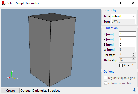
Fig. 31 Solid.
Geometry
Under Geometry you can select the Type. The following types are available for selection:
cuboidellipsoidcylindertubeconetext(to define a text marker that can be radiographed)wedgestep wedge
Dimensions
The size of the solid can be defined by the X, Y, and Z extent of its bounding box. By activating the checkbox X=Y (=Z) you can force equal values for X [mm], Y [mm], and Z [mm].
The W defines the wall thickness of a tube, or the final thickness (in Z dimension) of a wedge (Z sets the initial thickness). The Phi steps and Theta steps control the accuracy of the faceting of the ellipsoid, cylinder and cone.
Options
For an ellipsoid, you can additionally decide whether to use facetting in a regular ellipsoid grid using a latitude/longitude tesselation or a geodesic tesselation of equal-sized triangles (see Fig. 32).

Fig. 32 Latitude/longitude tesselation (left) and geodesic tesselation of equal-sized triangles (right).
For ellipsoid, cylinder, and cone, you can activate the volume correction, where the facetted solid will be scaled up to meet the exact volume of the ideal solid.
Note
The default material for new parts is Fe and can be adjusted at Menu Bar → Tools → Settings… → Advanced → Geometry. But text is always created with material Pb.
Tip
After the solid is created, it can also be saved in a file (STL or PLY). To do this, select the part of your solid in the Assambly List (e.g., by clicking at it in the scene) alone. Than use the general dialog File →  Save as … to save, selecting
 File type Selected Parts.