Multi-Component Parts
Each part on the Assembly List is a solid that can only have one single material. We can place multiple parts into the scene, each with a different material. In regions of space where these parts overlap, there is a strict hierarchy: objects that appear later in the Assembly List (towards the bottom) have a higher priority and completely replace previous objects (of lower priority). We can use this fact to build objects from components that all have different materials.
In this tutorial, we will create a small air pocket and place it inside the Rotor.
Note
We continue with the project from the “Materials” tutorial. You can download it here if you need the current state:
tutorial_materials.aRTist (4.6 MB)
Solid Module
The Solid module can generate simple geometric solids like spheres, cuboids, etc.
Note
In the Toolbar, click the button ![]() Generate simple geometric object or open the module from the menu bar: Modules → Solid.
Generate simple geometric object or open the module from the menu bar: Modules → Solid.
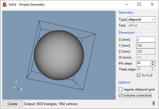
Fig. 74 We use the Solid module to create a sphere that we will use as an air pocket.
You can choose the Type of solid that you would like to generate. Examples for the available types are shown in Fig. 75. For each solid, you can tune its geometric properties. Typically, the aspect ratio can be controlled with the parameters X, Y and Z which specify the dimensions of the bounding box. W is an additional parameter that is sometimes necessary, for example to set the diameter of a tube’s inner hole or the size of the foundation of a wedge (i.e. the part that is not angled).
Phi steps basically controls the resolution of the solid’s mesh, or the number of steps on a step wedge. Theta steps is available for ellipsoids if you create a regular ellipsoid grid. In this case, phi and theta refer to the two angles of a spherical coordinate system.
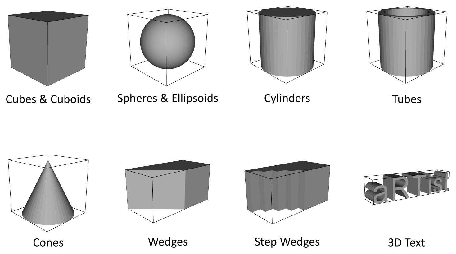
Fig. 75 The basic geometric solids that can be generated in the Solids module.
Note
Create a small sphere that we will use as an air pocket (Fig. 74).
Set Type to
ellipsoid.Activate X=Y=Z to generate an ideal sphere.
Make sure regular ellipsoid grid is deactivated.
For the diameter X, enter
2mm.For Phi steps, set
42to create a relatively smooth sphere.Click Create.
The sphere will appear with the name “ellipsoid” on the Assembly List. It is made of iron and will have a random colour.
Note
Click on the name of the “ellipsoid” and rename it to Air Pocket. Press Enter once you have typed the new name. Click on the Air Pocket’s current material (Fe) and choose air from the drop-down menu.
When you click  Zoom to Selection in the Toolbar, you should see the sphere, located in the centre of the detector at the origin of the coordinate system (Fig. 76).
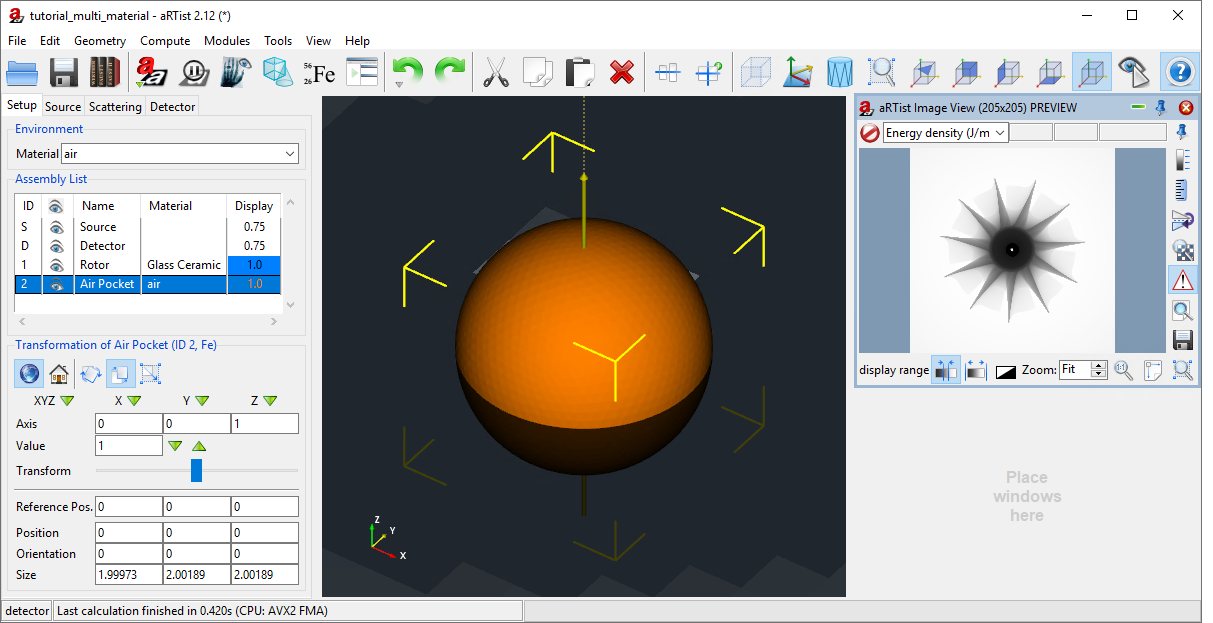
Fig. 76 We created a spherical ellipsoid, renamed it to Air Pocket, set its material to air and zoomed in to its current location at the coordinate origin.
Overlapping Parts
The Air Pocket appears after the Rotor in the Assembly List. Therefore, it has a higher priority and will replace the Rotor wherever they overlap. All we have to do now is move it into the Rotor.
Note
Enter the following Position for the Air Pocket: X: 4, Y: 3, Z: 200. Press Enter to set the position. (Fig. 77)
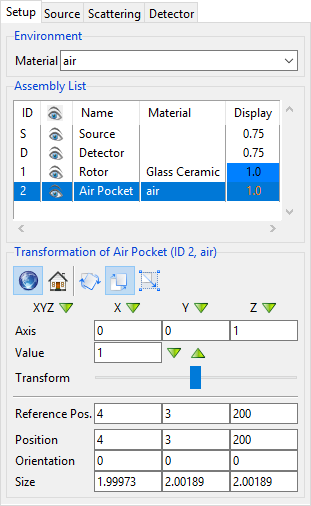
Fig. 77 We place the Air Pocket at coordinates inside the Rotor.
Note
To see the Air Pocket in the virtual scene, make the Rotor transparent: double-click on its colour in the Assembly List and decrease its Opacity (Fig. 78). Alternatively, you could switch its rendering mode to  Wireframe View.
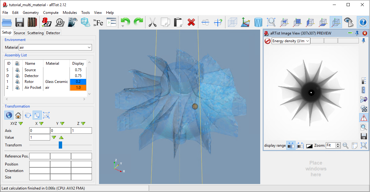
Fig. 78 We decreased the opacity of the Rotor to 0.2 to see the Air Pocket inside it in the virtual scene.
You should now also be able to identify the Air Pocket in the projection image that the Image Viewer displays. It is easier to see when you simulate a full projection image (click the  Compute button) and zoom in. You may even select a region of interest (ROI) to enhance the local contrast (Fig. 79).
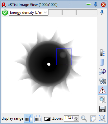
Fig. 79 The Air Pocket becomes visible in the projection image. A region of interest (blue rectangle) is selected to rescale the display range and enhance the local contrast.
Note
Toggle the visibility of the Air Pocket with its  visibility switch in the Assembly List. Observe how it disappears and reappears in the projection image. When you are done, please keep it visible so that you can still see it for the next step.
Order of Parts (Hierarchy)
As described at the beginning of this tutorial, parts that appear later in the list completely replace earlier parts in regions where they overlap. You can rearrange the parts on the Assembly List to establish a different order and therefore a different hierarchy of priorities.
Note
Click on the Air Pocket in the Assembly List and keep holding your mouse button. Drag the part one step upwards such that it will take a place before the Rotor. Release your mouse button to drop it there. (Fig. 80)
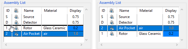
Fig. 80 We drag the Air Pocket to a position before the Rotor. (Left: while dragging, right: dropped.)
After we re-arranged the order of parts, the Air Pocket is not visible anymore in the projection image (Fig. 81). It is now completely replaced by the Rotor material because the Rotor has a higher priority. Also note that each part keeps its unique part ID (Rotor: 1, Air Pocket: 2). This ID is used by some modules to refer to parts. It is independent from the part order and will not change.
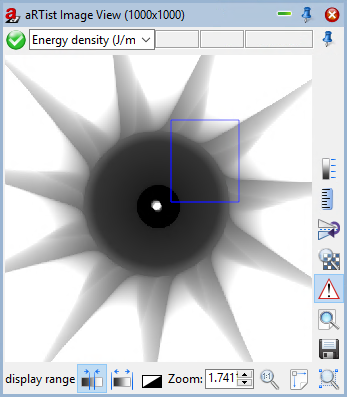
Fig. 81 The Air Pocket disappeared from the projection image as it is replaced by Rotor material.
Note
Move the Air Pocket back to its previous position underneath the Rotor in the Assembly List. It should now appear again in the projection image. (As we saw in Fig. 79.)
Transforming Groups of Parts
While aRTist doesn’t provide the ability to permanently group parts, you can select multiple parts on the Assembly List and transform them all at the same time. They will then keep their relative positions. You can choose multiple parts by pressing Ctrl while selecting them with a click.
The first part you select will be displayed with a yellow-cornered bounding box in the scene view. Any additional parts selected after that will get a white-cornered bounding box. The first selected part is special: its centre will be the centre of rotation or scaling for the whole group of parts. Alternatively, you may enter a different reference position after you have selected all the parts.
Let’s try this. First, we rotate the Rotor around its central axis together with the Air Pocket.
Note
Click on the Rotor in the Assembly List.
Hold down the Ctrl key on your keyboard while you select the Air Pocket.
Both the Rotor and the Air Pocket should now be selected. There should be a yellow-cornered bounding box around the Rotor and a white-cornered bounding box around the Air Pocket (Fig. 82).
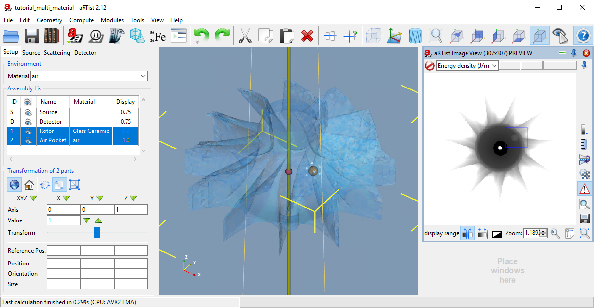
Fig. 82 We have first selected the Rotor, then the Air Pocket.
Note
Under Transformation of 2 parts, select the
 world coordinate system. (This is important: if you select local instead, each part will rotate around its own axis instead of a common axis.)
Select the
 Rotation Mode.
Select the
 Z axis.
For the Value, enter
45degrees.Click to the right of the transform slider handle to perform one rotation step.
Both the Rotor and the Air Pocket should now rotate around the Rotor’s central axis and keep their relative positions. This means that the Air Pocket travels by 45° in counter-clockwise direction in the projection image. (This is because the Z vector points away from the detector towards the source.)
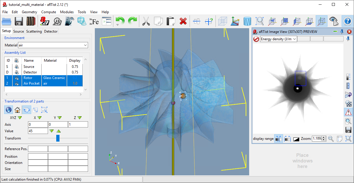
Fig. 83 We rotated both parts around the common central axis of the Rotor.
We have not set any reference position, which means that the centre of rotation is the centre of the first-selected part (the Rotor). Let us now set a different Reference Position.
Note
For the Reference Pos., enter the following coordinates: X: 0, Y: -15, Z: 200. Press Enter to set it.
The reference position (displayed as a red sphere in the virtual scene) now moves to the new coordinates away from the Rotor’s centre (Fig. 84). The axis of rotation (still pointing in the direction of the Z axis of the world coordinate system) is drawn as a yellow vector through the reference position.
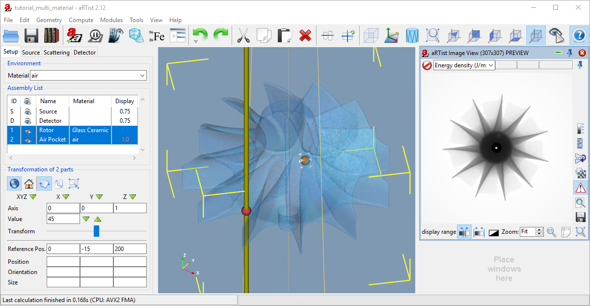
Fig. 84 We moved the reference position away from the Rotor’s centre.
We can now use this new reference position as the centre of rotation.
Note
In the Image Viewer, click
 Zoom to fit window to see the whole projection image again. (Just in case you zoomed in previously.)
Click 8× to the right of the transform slider to perform one full rotation of the group of parts. Observe how they both rotate around the reference position, both in the virtual scene and in the projection image. They keep their positions relative to each other.
You can also use the reference position as the scaling centre; this works in the same way. And, of course, you can also use the Transformation controls to translate selected parts as a group.
Summary
In this tutorial, we have demonstrated how to create simple geometric solids and how to handle assemblies of multiple components.
You know about the Solid module and how to use it to create simple geometric solids.
You have learned that the order of parts on the Assembly List plays an important role in regions where parts overlap. Parts at positions later on the list (further to the bottom) replace parts that are earlier on the list.
You have selected multiple parts using the Ctrl key on your keyboard.
You know that the first part that you select has a special role: its centre will be the reference position for rotations and scalings, unless you set a different one.
You have learned how to use the reference position as a centre of rotation (or scaling) for groups of objects.
tutorial_multiple_components.aRTist (4.6 MB)