Position, Orientation & Size
Note
We continue with the project from the last tutorial. You can download it here if you need the current state:
tutorial_virtual_scene.aRTist (4.6 MB)
Local and World Coordinate Systems
In the previous tutorial, we have already seen that aRTist puts the detector by default at the origin of the coordinate system and the source at some point in positive z direction. This main frame of reference is called the world coordinate system. You can imagine it as a fixed frame, or stage, that is absolute and will never change.
When placing objects into the scene, we can express their position and orientation in terms of the world coordinate system. In aRTist, the position of an object is a tuple of three coordinates (x, y, z) that refer to the position of the object’s centre (i.e. the centre of its bounding box) in the world coordinate system. This centre point is the origin of the object’s local coordinate system.
Each object comes with three intrinsic axes. More specifically, the coordinates of the triangles in the surface mesh of an STL or PLY file are expressed in terms of its own Cartesian coordinate system. The axes of this intrinsic coordinate system must not necessarily align with aRTist’s world coordinate system, as illustrated in the example of the tilted Rotor in Fig. 58.
When an object rotates in space, the directions of the three axes of its local coordinate system change in relation to the world coordinate system. Mathematically, we can express the local axes as vectors within the world coordinate system to know an object’s orientation.
In the example illustrated in Fig. 58, the detector’s local coordinate system {XD, YD, ZD} has the same origin and alignment as the world coordinate system. The source’s local coordinate system {XS, YS, ZS} has the same alignment, but its origin is at a different point in the world coordinate system, somewhere along the positive Z axis. The Rotor’s local coordinate system has also a different origin, and additionally a different alignment (orientation) relative to the world coordinate system.
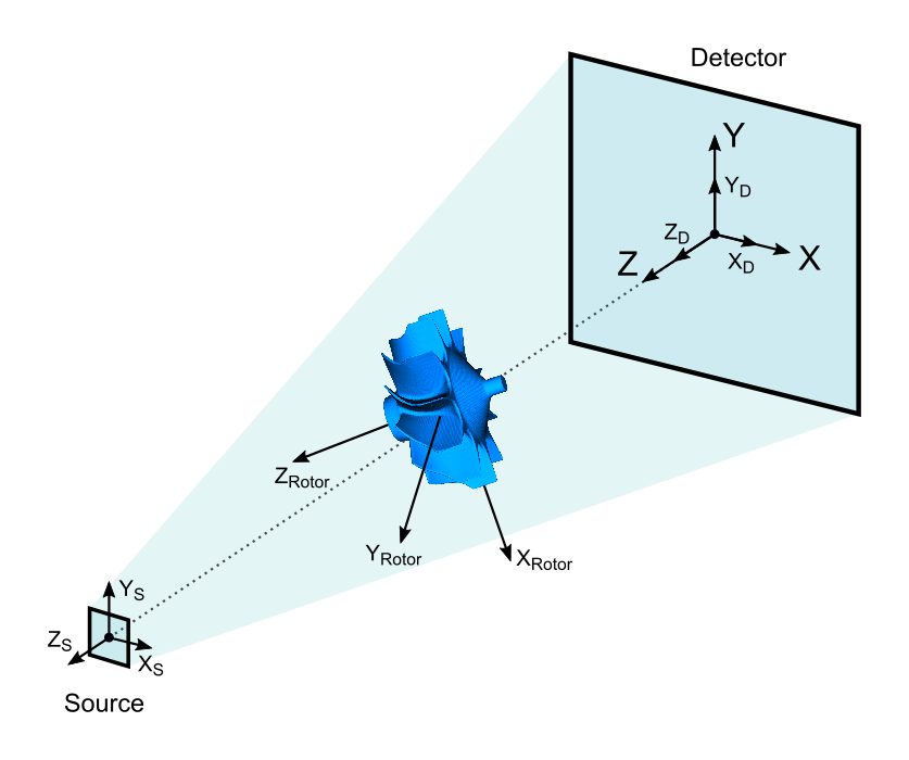
Fig. 58 The world coordinate system {X, Y, Z} and the local coordinate systems of the three objects in the scene.
Parameter Panel
If we take a look at the full scene again, we see that the source seems to be a little bit close to the detector.
Note
Deselect the rotor by clicking on the unoccupied white area in the Assembly List or on the brackground colour in the Virtual Scene. Now click on  Zoom to Selection to see the full scene again.
We already know that the detector is at the origin of the world coordinate system: its centre lies at the point (0, 0, 0) in space. You can check this by selecting the Detector item from the Assembly List and inspecting its properties in the Transformation section of the Parameter Panel (Fig. 59).
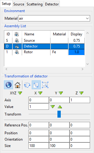
Fig. 59 The lower three rows of the Parameter Panel show the position, orientation and size of the selected Detector.
The panel also tells us that the detector has a Size of 100 mm in X direction and 100 mm in Y direction. It has no thickness (0 mm in Z direction). The size always refers to an object’s bounding box, i.e. its local coordinate system. In the case of our specific detector, the axes of its local coordinate system and the world coordinate system point in the same direction. In general, this is not the case for any object.
We can also get the information about the position of the source.
Note
Select the Source from the Assembly List and check its Z position.
The source is located 100 mm away from the detector on the Z axis.
Position
In the field of computed tomography, two very important parameters of a system’s geometry are the source-detector distance (SDD) and the source-object distance (SOD). We will now change our scene to get the geometry shown in Fig. 60, with an SDD of 500 mm and an SOD of 300 mm.
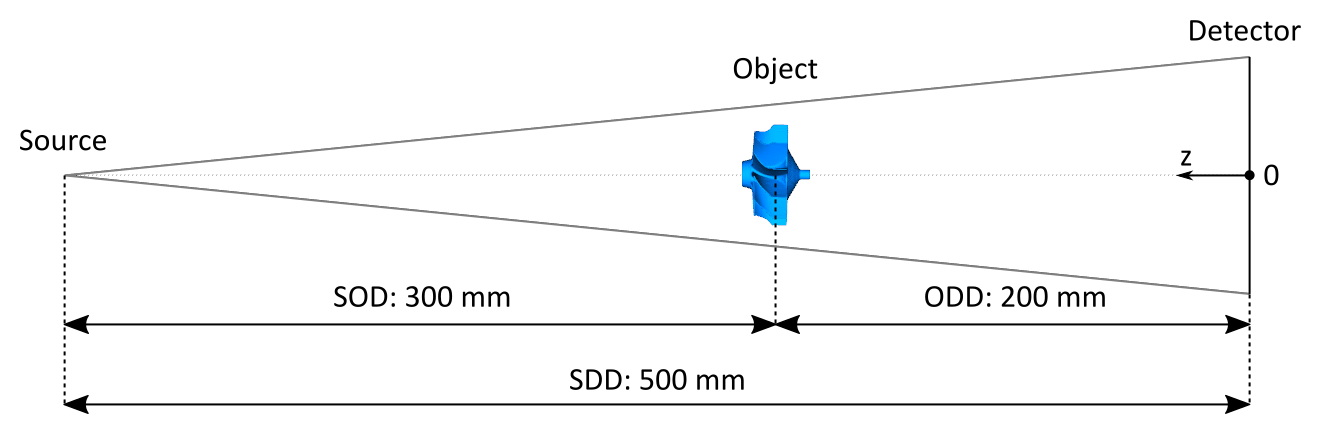
Fig. 60 Illustration of the geometry that we want to set up.
Setting up the SDD is the easier part. We have to place the source at the position Z = 500 mm, because the detector is located at the origin of the world coordinate system and we want to keep the convention to place the source in positive Z direction.
Note
Select the Source from the Assembly List. Set 500 for the Z coordinate of the Position (Fig. 61) and press Enter.
The number in the input field will be displayed in blue until it is applied to the scene.
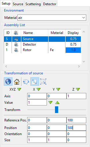
Fig. 61 Placing the source at 500 mm. The number remains blue until we press Enter to apply the change.
The Rotor is still at the origin of the coordinate system, basically “inside” the detector. To move it to the correct SOD of 300 mm, we have to keep in mind that we need to set its position on the Z axis, which starts at the detector. This means that we have to calculate the object-detector distance (ODD) first:
ODD = SDD – SOD = 200 mm.
We can now place the Rotor 200 mm away from the detector to get the required SOD of 300 mm.
Note
Select the Rotor from the Assembly List and set its Z position to 200. Press Enter.
When you take a look at the full view of your scene, it should now look like in Fig. 62.
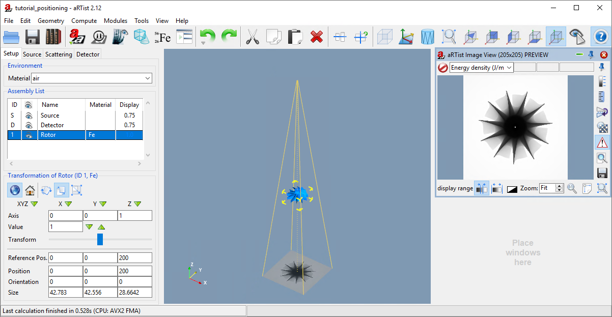
Fig. 62 We have changed the geometry to an SOD of 300 mm and an SDD of 500 mm.
To set up horizontal and vertical shifts, you can change the X position and Y position of any object in the same way.
Orientation
One row below the Position settings in the Parameter Panel you can set the Orientation. This is a set of three angles (in degrees) that represent consecutive rotations around an object’s coordinate axes.
Whenever you load a new object into the scene, the axes of its local coordinate system are aligned with the axes of the world coordinate system. To reach the orientation specified by the three angles, aRTist will perform three rotations of the object in the following order.
The object is rotated by the third angle around its local Z axis.
The object is rotated by the first angle around the resulting local X axis.
The object is rotated by the second angle around the resulting local Y axis.
Note
Select the Rotor and set its orientation angles to X: 20, Y: 30 and Z: 10. Press Enter to apply the orientation.
You should now see a tilted Rotor in the virtual scene, just like in Fig. 63. Starting with its local coordinate system aligned with the world coordinate system, it has first been rotated by 10° around its local Z axis, then by 20° around the resulting local X axis, and thirdly by 30° around the resulting local Y axis.
The order in which you enter the three Orientation angles does not matter for the final result. Whenever you change an orientation angle, aRTist will internally reset the object to its original orientation, and then strictly rotate it in the given order Z→X→Y.
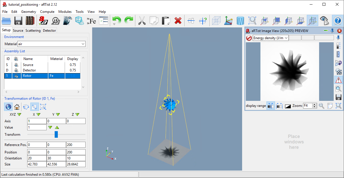
Fig. 63 We have changed the orientation of the Rotor in the scene.
Often, using the Orientation angles directly can be very inconvenient because of the strict order of rotations. An easier and more powerful way to transform an object’s position and orientation are incremental transformations as explained in the next section.
Incremental Transformations
The upper part of the Parameter Panel provides a lot of options to transform an object. Fig. 64 gives an overview over the buttons and input fields.
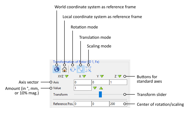
Fig. 64 The transformation controls of the Parameter Panel.
Rotations need an axis of rotation, and translations need a translation vector that points in the direction of the movement. Such an axis is provided as a three-component vector that you can enter under Axis. The buttons X ![]() , Y
, Y ![]() and Z
and Z ![]() provide easy ways to set the standard vectors for X, Y and Z direction. XYZ
provide easy ways to set the standard vectors for X, Y and Z direction. XYZ ![]() gives you a diagonal axis.
gives you a diagonal axis.
The important question is: does the vector describe a direction in the world coordinate system or in the local coordinate system of the object you selected? You can choose the one you prefer: in the upper part of the panel, either click the button for the  world coordinate system or for the object’s
  local coordinate system.
Next to the two buttons for the coordinate systems you can choose which kind of transformation you want to perform. There are three buttons to choose  Rotation Mode,
  Translation Mode (move) or
  Scale Mode (resize).
For Value, you can set the amount by which you want to rotate, move or scale. For rotations, enter an angle in degrees. For translations, enter a distance in mm. For scaling, aRTist expects a factor that expresses a multiple of 10% magnification, i.e. a factor of 1 will increase the object’s size by 10% in the given direction.
To apply the transformation, you can use the transform slider. When you grab the handle and drag it across the slider, it might perform several consecutive transformations. If you want exactly one transformation step, you have much better control by clicking onto the horizontal slider bar to the left or to the right of the slider handle.
A click on the right side of the slider handle leads to a positive transformation by the amount you entered. This means that rotations will happen in a mathematically positive direction around the axis vector and translations will move the object in the direction of the axis vector. Scalings will multiply the size of the object by the given 10%-magnification-factor.
A click on the left side of the slider handle leads to a negative transformation by the amount you entered. This means that rotations will happen in a mathematically negative direction around the axis vector and translations will move the object in the opposite direction of the axis vector. Scalings will divide the size of the object by the given 10%-magnification-factor.
Normally, the centre of rotation or scaling is the centre of the object’s bounding box. You can change this point by entering a different Reference Position underneath the transform slider.
Note
Let’s put this in action. We will now reverse the Rotor’s orientation using the transform slider. But first: now is a good moment to save your project, just in case you make a mistake.
Make sure the Rotor is selected.
Select the
Local Coordinate System as the reference frame. (Remember that aRTist assumes that the orientation angles refer to consecutive rotations around the three axes of the object’s local coordinate system.)Switch to
Rotation Mode.Click on Y
 to select the Y axis. (This has been the last of the three rotations. We need to go in reverse order to get back to the start.)
For Value, enter
30.Click to the left of the transform slider handle to perform one transformation step in the opposite direction (a rotation of -30° degrees, if you will).
Click on X
to select the X axis.For Value, enter
20.Click to the left of the transform slider handle.
Click on Z
to select the Z axis.For Value, enter
10.Click to the left of the transform slider handle.
You should now be back at an orientation of (0, 0, 0) and see the view from Fig. 62 again. If you would have changed the order of rotations, you would not be back at this point.
Summary
In this tutorial, you have learned how to change the position and orientation of objects.
You know that each object has its own local coordinate system in a fixed, unchanging reference frame that is called the world coordinate system.
You can set the position and orientation of objects.
You learned that the three orientation angles are always applied in the order Z→X→Y of the object’s local coordinate axes.
You are able to use the transform slider to apply rotations around any given vector, and translations in any direction.
tutorial_positioning.aRTist (4.6 MB)