The Virtual Scene
A Blank Scene
When you start aRTist, it will show you an empty scene (Fig. 50). There is a detector and a source, and the rest is invisibly filled with air, the standard environment material.
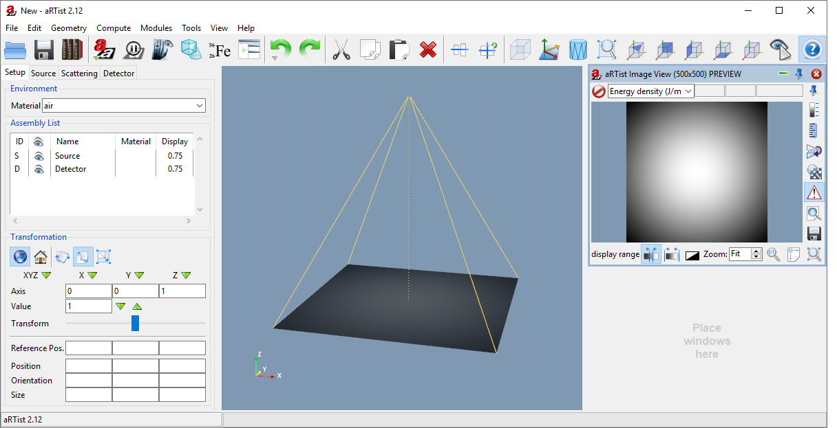
Fig. 50 The aRTist window with a blank scene.
aRTist’s standard coordinate system is shown in Fig. 51. The detector is placed at the origin of the world coordinate system. The source is located at a positive point somewhere along the Z axis. For a standard CT set-up, the axis of rotation would point in the direction of the Y axis.
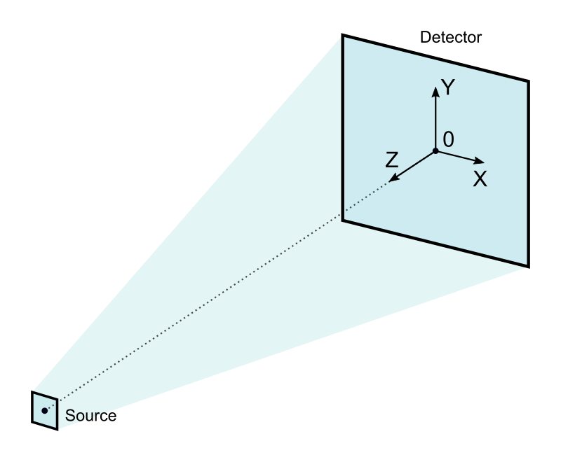
Fig. 51 aRTist’s standard coordinate system
You are free to change the position and orientation of any of the components in a scene, including the source and the detector. Some modules, like the CtScan module that we will use later, assume a certain coordinate system, for example that the Y axis is the axis of rotation. To stay on the safe side, it may be a good idea to stick with this convention.
Note
Use your mouse to change the view. Left-click and drag in the virtual scene to change the camera’s view point. Right-click and move the mouse up and down to zoom. Middle-click (typically your mouse wheel) and move the mouse to shift the view on the screen.
Loading Objects
Any sample simulated in aRTist is represented as a 3D surface model (triangular mesh) that encloses a volume. You are able to load STL, PLY, OBJ and VTK files as objects into the scene. To load objects, you can drag and drop a file into the aRTist window, or use the  Open button from the toolbar or use the menu: File → Open…
aRTist comes with a sample library that contains some surface models that we can already use. Let’s load the Rotor.
Note
Click the  Library button in the toolbar or choose from the menu: File → Open Library….
Load the Rotor surface model from ExampleParts → Rotor.ply.
The rotor is loaded and placed into the scene at the center of the detector, because that is the origin of the coordinate system (Fig. 52). Additionally, the rotor appears on the left-hand side in the Assembly list of the Parameter panel. It gets a random colour and the default material is iron (Fe).
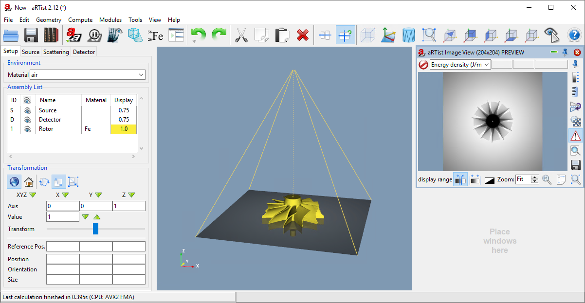
Fig. 52 The rotor is loaded into the scene.
If you want to load a surface model at its native position (as defined in the file) instead of centred at the origin of the coordinate system, turn off the button  Center new parts in the toolbar or turn it off in the menu: Geometry → Center New Parts.
Colours of Objects
To change the colour of an object in your scene, find your object in the Assembly list and double-click on the colour in the list’s Display column. The number shown in this column represents the object’s opacity (transparency).
Note
Double-click on the rotor’s colour.
The Display Parameters open (Fig. 53). There, you can choose a new colour by clicking the  Colour Wheel. You can also set up transparency with the Opacity slider. The parameters Diffuse, Specular and Power control the object’s ability to cast shadows and its “shininess”. For details, take a look at the Phong reflection model.
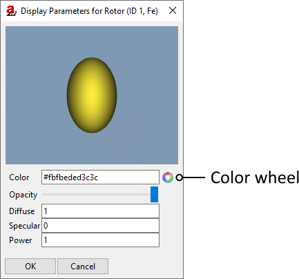
Fig. 53 The Display Parameters let you change the colour and appearance of an object.
Note
Select a colour that you like for the rotor. I’ll choose blue.
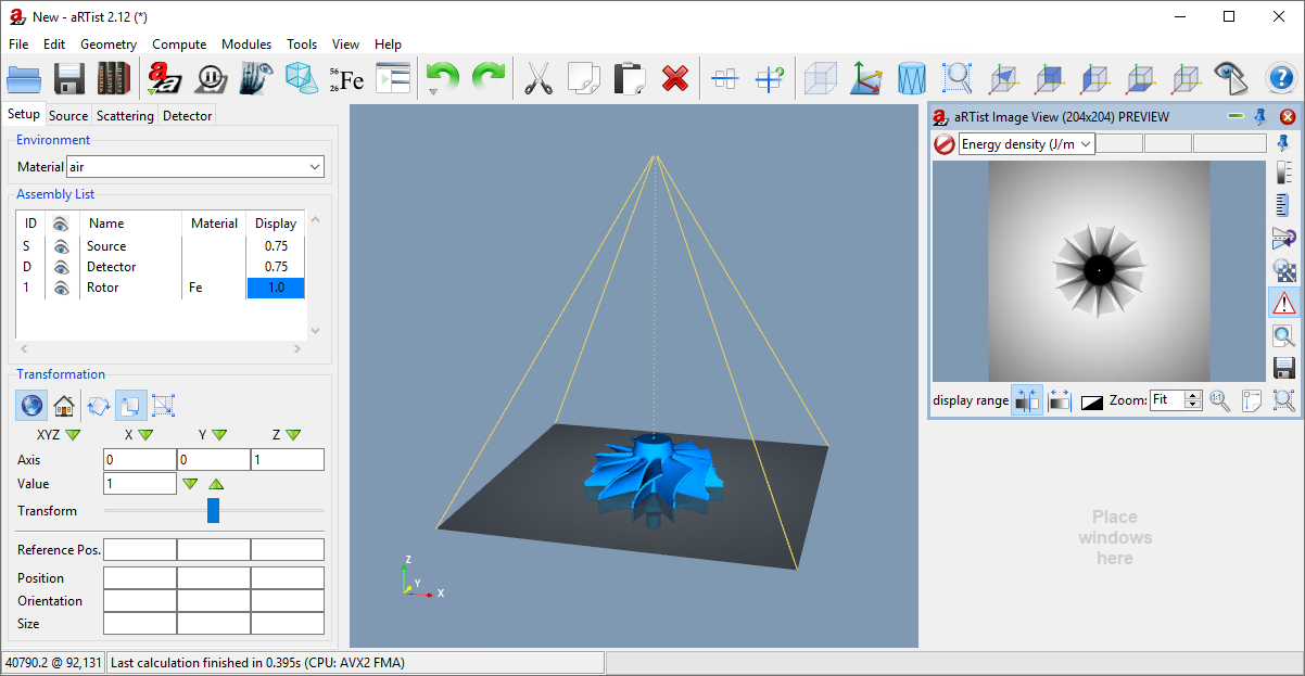
Fig. 54 We have changed the colour of the rotor.
Saving a Project
You can save your current work as an aRTist project. These have the file extension .aRTist and they contain everything from your scene in one file: all object definitions, their materials, the detector and source settings, etc. You will not need any additional files to open your complete project again at a later time.
Note
Click the  Save button in the toolbar or choose from the menu: File → Save. Select a folder and name for your project and save it.
Save frequently! There will be no further reminders ;-)
View & Display Options
Take a look at the buttons in the right section of the toolbar. They provide some functionality to change the view:
Some of these only work once a part is selected.
Note
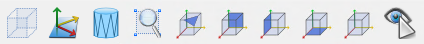
Select the rotor: either click on it in the Assembly List or click on it in the scene. It should now be highlighted in the Assembly List and a bounding box with yellow corners should appear that encloses the Rotor in the virtual scene (Fig. 55).
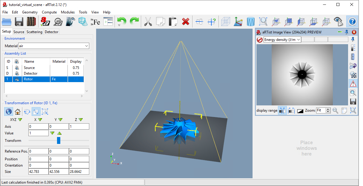
Fig. 55 The Rotor is selected: it is highlighted with a blue background in the Assembly List and enclosed in a yellow-cornered bounding box in the virtual scene.
View Directions
The following buttons change the view such that the camera looks either from the top right direction or directly along one of the axes of the coordinate system.
 View from top right
 View along X
 View along Y
 View along Z
They can be clicked once or twice. Clicking them a second time will change the view to the opposite direction.
 Orthographic/perspective projection
With this button, you can switch between orthographic projection and perspective projection. In an orthographic projection, all parallel lines appear parallel and object size does not decrease with distance. In perspective view, parallel lines do not appear parallel on screen, but they meet in a common view point at infinity.
All of these commands can also be found in the View menu.
 Zoom to Selection
This button zooms in or out to fit the selected part(s) into the view. If no part is selected, it will arrange the view such that everything can be seen at once.
You can also find this function in the menu bar: View →  Zoom to Selection
Note
Change the view to top right, then zoom in to the selected rotor (Fig. 56).
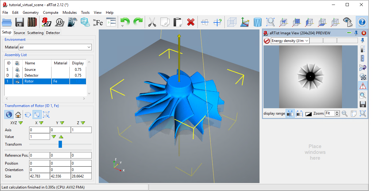
Fig. 56 We have zoomed in to see the selected rotor and changed the view direction to top right.
 Bounding Box
You can use this button to draw a permanent bounding box around the object. At the moment, it is only displayed by yellow corners as long as the rotor is selected. This functionality lets you always display the bounding box, no matter if the part is selected or not. A full frame will appear in the object’s colour.
 Axes View
Each part has its own, local coordinate system. With this button, you make the local axes visible. The X axis will be displayed as a red line, the Y axis as a yellow line, and the Z axis as a green line.
 Wireframe and Solid View
Instead of viewing a part as a solid surface, you can use this button to display a wireframe model of the triangular mesh. The Rotor has a lot of triangles, so you will need to zoom in to see the detailed wireframe mesh (Fig. 57). On less powerful computers, a reduced mesh will be displayed (possibly even instead of the solid model).
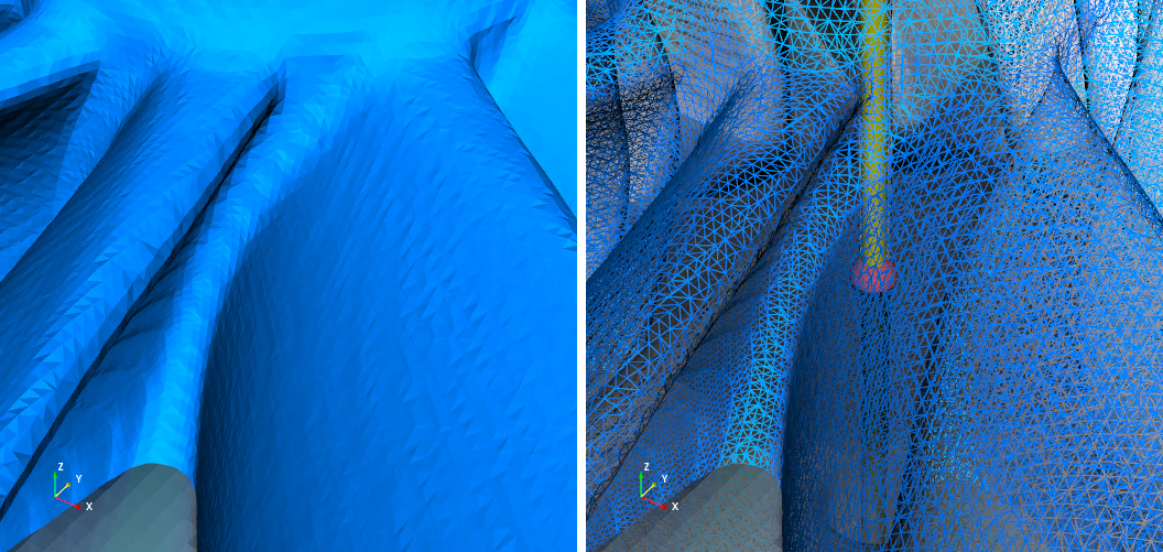
Fig. 57 Solid surface (left) and wireframe view (right).
Object Visibility
The visibility of an object can be turned on and off by clicking the  eye symbol in the Assembly List. Any sample other than the source or the detector that has been turned off will not be considered during the simulation of the X-ray projection.
Note
Click the eye symbol next to the Rotor in the Assembly List. In the Virtual Scene, it will be rendered in a highly transparent way, and it will disappear from the projection preview in the Image Viewer on the right side of the window. Turn it back on by clicking the  eye symbol (now grey) again.
If you feel that the scene looks too cluttered with the detector and the lines connecting its corners to the source, you can also turn off the visibility of the Source or the Detector in the Assembly List. Their visibility will not affect the simulation of the projection image in any way.
Summary
In this tutorial, you have learned about aRTist’s virtual scene and how to arrange it.
You know about the standard coordinate system and that, for the moment, we don’t want to change the principal axes.
You have learned how to load surface files into the virtual scene and you have made use of aRTist’s library to import the Rotor.
You assigned a colour to an object.
You know that a saved aRTist project contains everything you need to restore it at a later point (including all surface models).
You have also learned how to navigate around the view, change the camera position, projection mode, and some rendering options.
You know how to turn the visibility of objects on and off and that only visible objects are considered during a simulation (with the exception of Source and Detector).
tutorial_virtual_scene.aRTist (4.6 MB)